GD&T defines permissible deviations for linear or angular dimensions to fulfill drawings geometrical requirements.
Introduction to GD&T (Geometric Dimensioning and Tolerancing)
GD&T, which stands for Geometric Dimensioning and Tolerancing, defines permissible deviations for linear or angular dimensions to meet the geometrical requirements specified in drawings.
When functional requirements necessitate specifying the geometrical accuracy of an element, tolerances are assigned to one or more characteristics of that element.
In certain cases, other required characteristics may be limited for certain types of tolerances. For instance, straightness may be limited by parallelism, but parallelism is not limited by straightness. Therefore, it is not necessary to define all characteristics on the drawing in such cases.
Additionally, for some tolerance zones (e.g., straightness in one direction), there are two possible methods of graphic representation, such as using two mutually parallel planes presented in three-dimensional orientation (as shown in sketch 1).
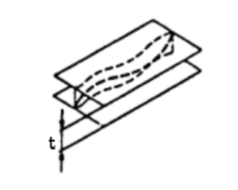
Sketch 1.
- By two mutually parallel straights projected on the plane (sketch 2.)
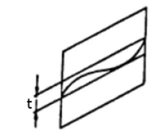 Sketch 2.
GD&T – Geometric Dimensioning and Tolerancing classification
There are several types of geometrical characteristics. They are classified in four groups defined as form, orientation, location, runout – as shown detailed in below classification
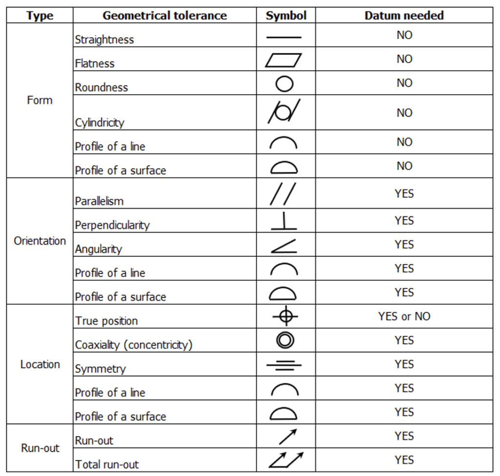 Table 1. – Geometrical tolerances with symbols and info about necessity to use datums. Editable version available for download here.
Explanation of some geometrical tolerance
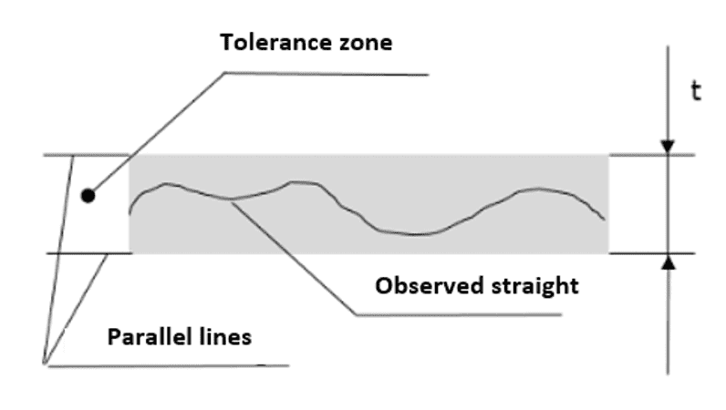
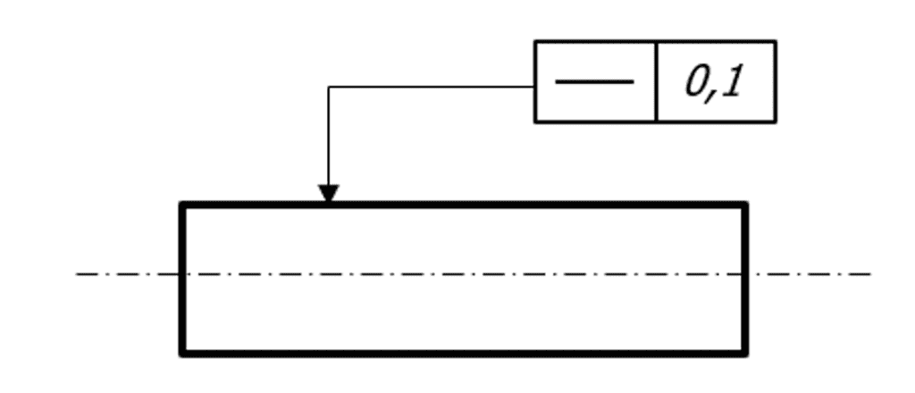
Straightness
Interpretation: Tolerance zone is defined by two parallel lines spaced by tolerance zone “t”, when tolerances are required only in plane.
 Drawing example:
Each forming line of observed surface should be between two parallel lines spaced by 0,1mm
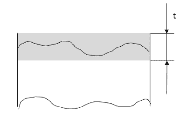
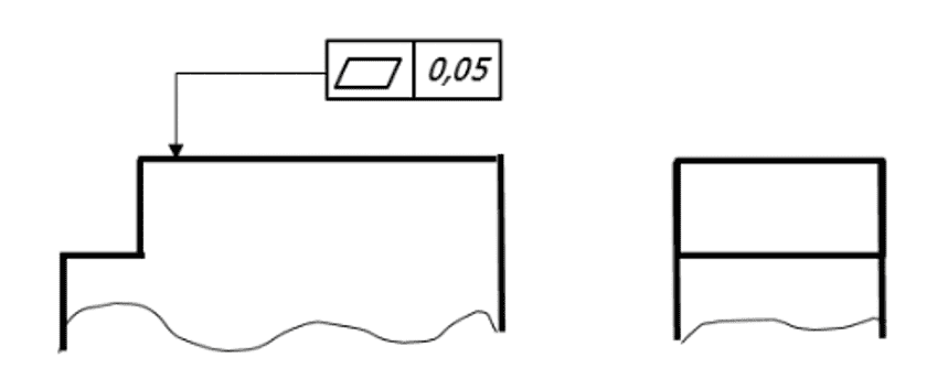
Flatness
Interpretation: Tolerance zone is defined (limited) by two parallel planes spaced by tolerance zone “t”.
Except that there are exceptional cases, as example: plane observed only convex and non-convex.
 Drawing example:
Observed surface must be between two parallel planes spaced by 0,05mm
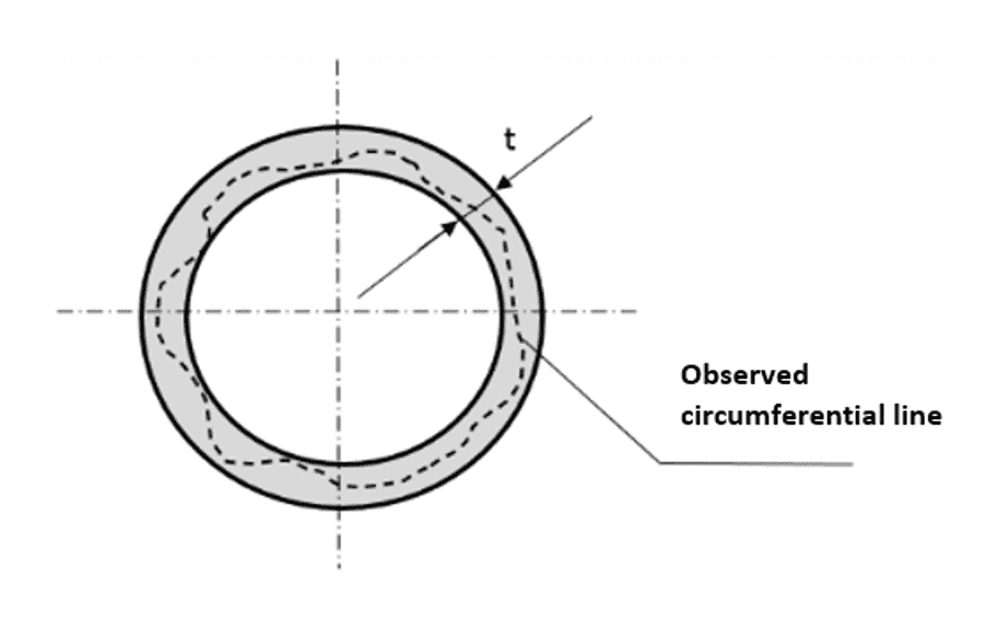
Roundness
Interpretation: Tolerance zone in each cross-section perpendicular to central axis is defined (limited) by two concentric circles with radius difference “t”
 Drawing example:
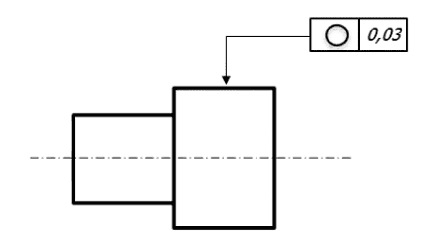 Observed cross-section surface must be between two concentric circles spaced by radius difference 0,03
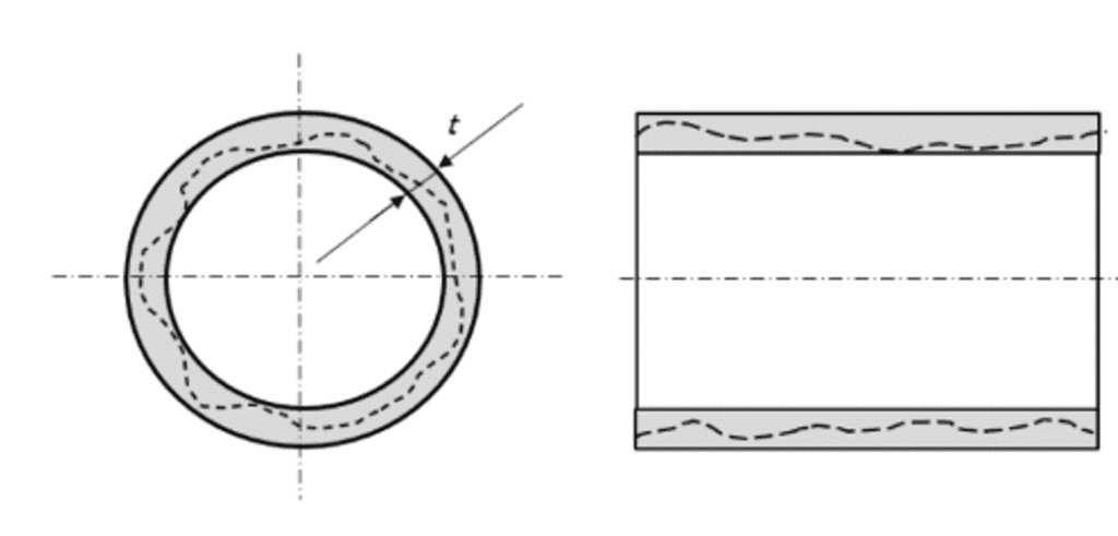
Cylindricity
Interpretation: Tolerance zone is defined (limited) by two coaxial cylinders with radius difference “t”
 Drawing example:
Observed cylindrical surface must be between two coaxial cylinders spaced by radius difference 0,01.
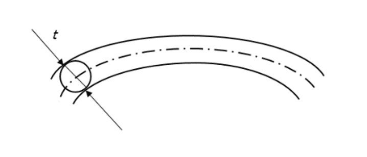
 Profile of line
Interpretation: Tolerance zone is defined (limited) by two lines determined by the envelopes of circles with diameter “t”, whose center points are located on theoretically exact profile.
Drawing example:
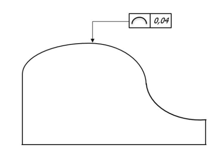 Observed profile must be between two parallel curves of a theoretically exact shape of controlled profile and spaced by 0,04mm
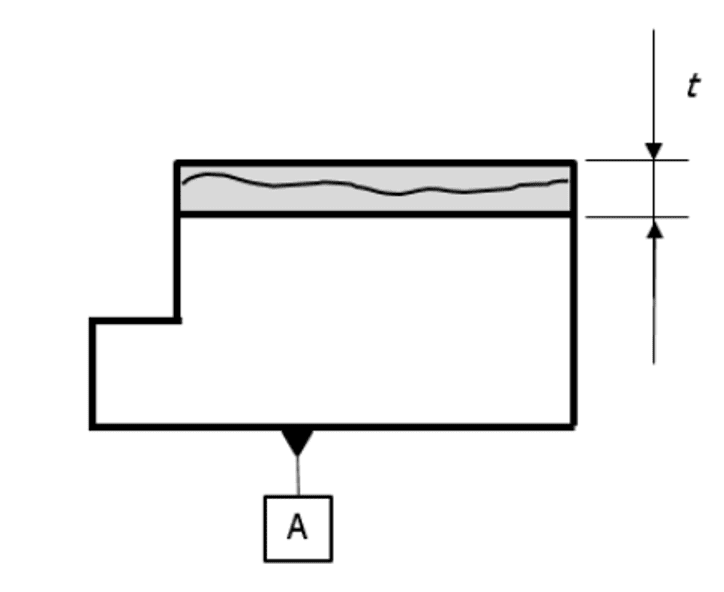
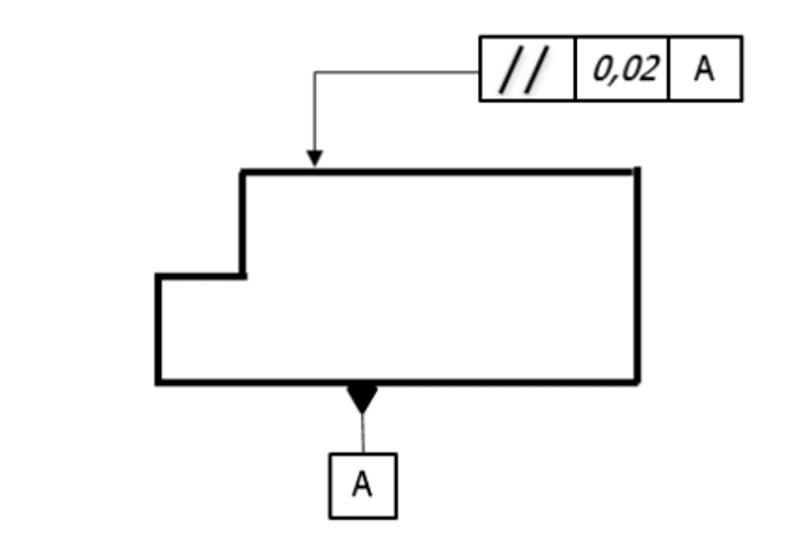
Parallelism
Interpretation: Tolerance zone is defined (limited) by two parallel planes spaced by “t” and parallel to datum A. In shown example there is requirement related only to one datum.
 Drawing example:
Tolerance zone is defined (limited) by two planes mutually parallel, spaced by 0,02mm and parallel to datum A.
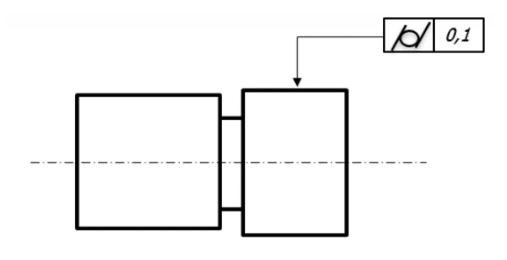
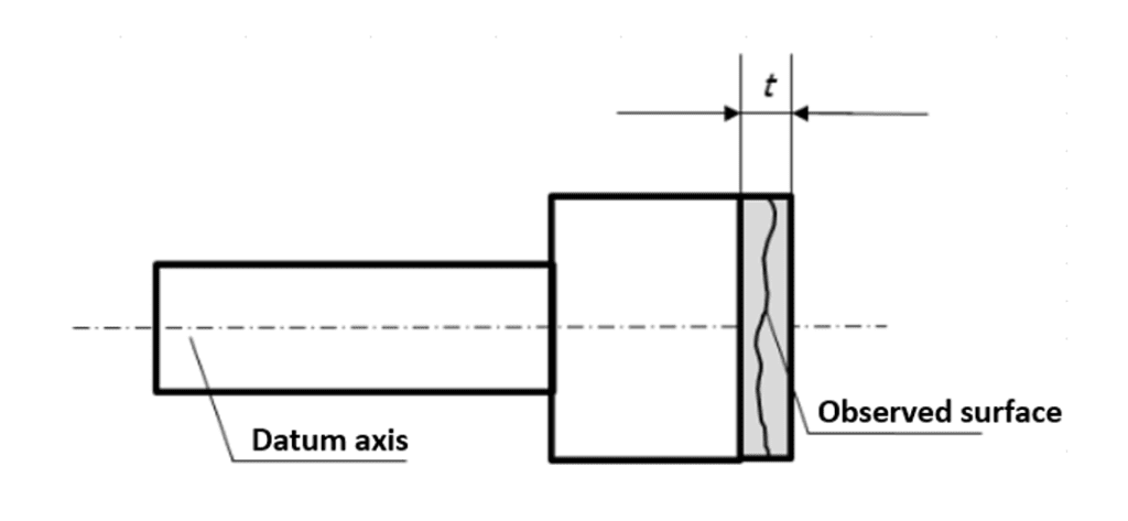
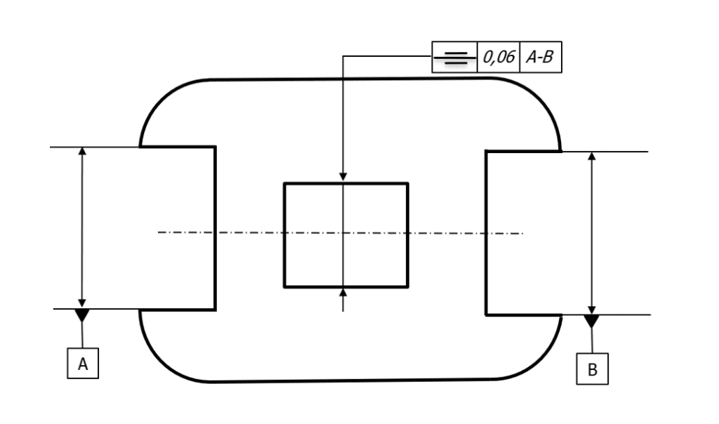
 Perpendicularity
Interpretation: Tolerance zone is defined (limited) by two parallel planes spaced by “t” and perpendicular to reference datum
 Drawing example:
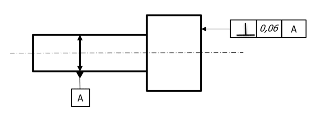 Observed surface must be between two parallel planes spaced by 0,06mm and perpendicular do datum A.
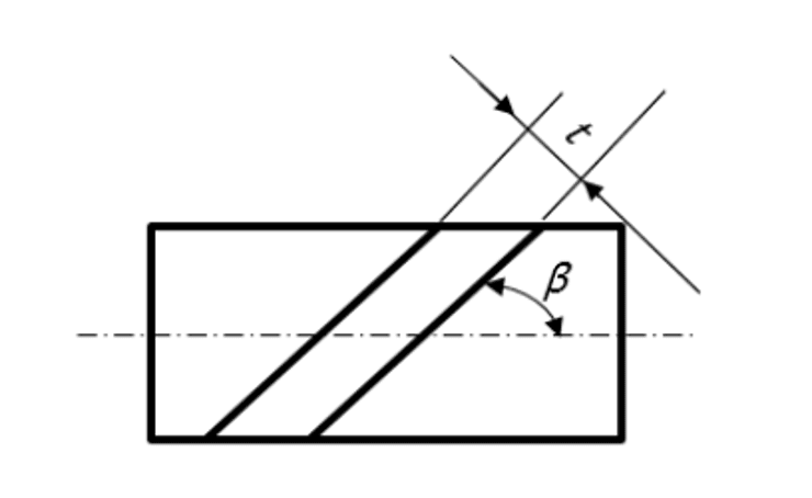
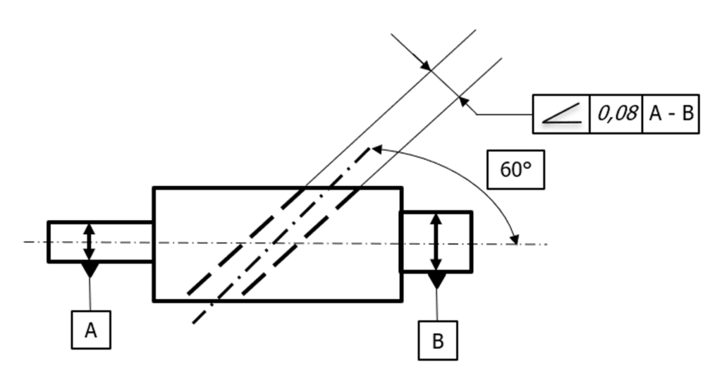
Angularity
Interpretation: Tolerance zone is defined (limited) by two parallel planes spaced by “t” and oriented at the specific angle “β” to reference datum.
 Drawing example:
Hole axis must be between two parallel planes spaced by 0,08mm and oriented at angle 60° to datum A-B (reference axis)
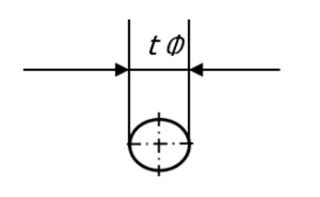
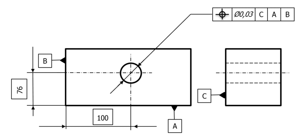
True position
Interpretation: Tolerance zone is defined (limited) by circle with diameter “t” placed in theoretically exact position.
 Drawing example:
Hole center point must be inside cylindrical tolerance zone with diameter 0,03mm whose axis is perpendicular to datum C and is located 76 mm form datum A and 100mm from datum B.
 Symetry
Interpretation: Tolerance zone is defined(limited) by two parallel planes spaced by “t” and placed symmetrically to mid plane
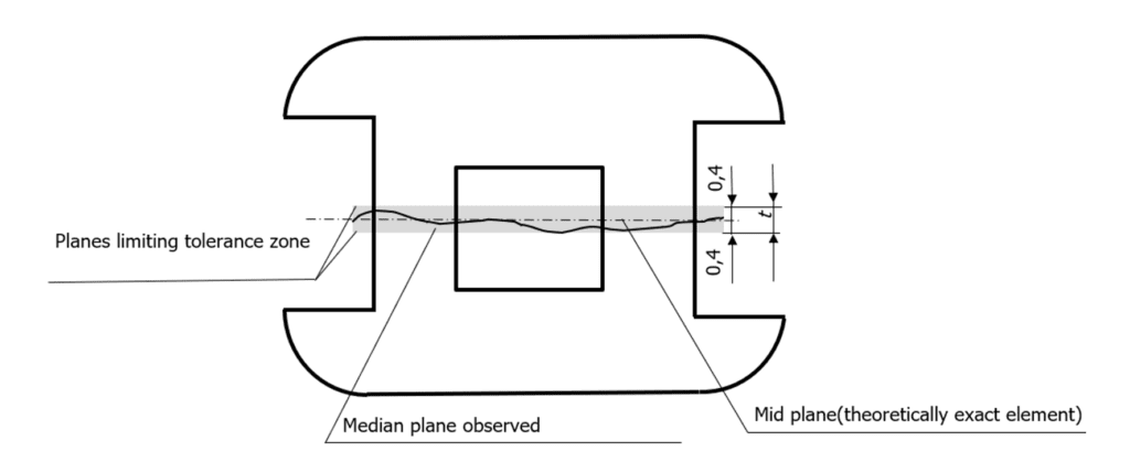 Drawing example:
Mid plane of groove must be between two parallel planes spaced by 0,08mm and oriented symmetrically to datum A-B (reference axis).
 Runout
Interpretation: Tolerance zone is defined (limited) in each cross-section by two concentric circles with radius difference “t” orientated on reference axis
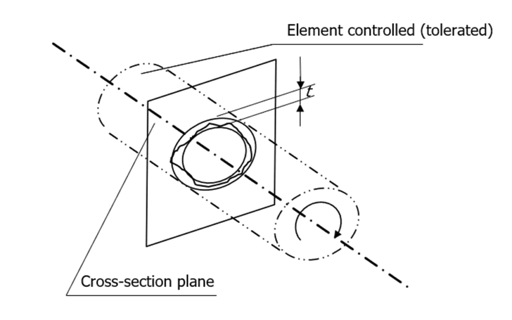 Drawing example:
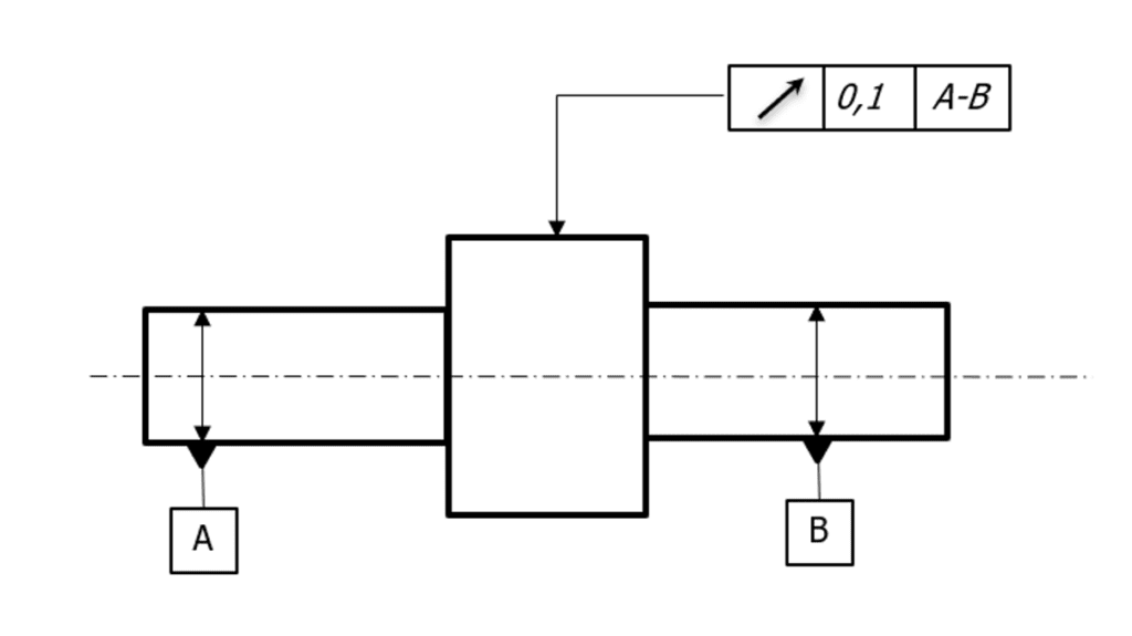
Observed surface in each cross-section must be inside of tolerance 0,1mm when the datums A & B are fixed axially and part is rotated all times
GD&T – Geometric Dimensioning and Tolerancing – Summary
Geometrical tolerances are identified on drawing by tolerance frame. There is always placed symbol of tolerance, value of tolerance(limit), info about datums (if needed).
Tolerance frame need to be always connected with an indication line (arrow) to the tolerated (checked) element.
Tomasz Skęczek